Geometry Connector
 Combines multi-element connect,
multi-element regression tools and connection editor into one tool.
Combines multi-element connect,
multi-element regression tools and connection editor into one tool.
You can access this tool from the following:
Ribbon: Geometry > Horizontal > Complex Geometry.
Geometry Connector dialog
If launching Geometry Connector tool from OpenRail the Begin Element options are turnout or element.
Possible connection combinations are turnout to turnout, element to element or turnout to element.
If launching Geometry Connector tool from OpenRoads and OpenSite the Begin Element options are alignments.
Select Begin Element and End Element then provide the geometry between. Compute a connection between two fixed or free elements as specified with parameters.


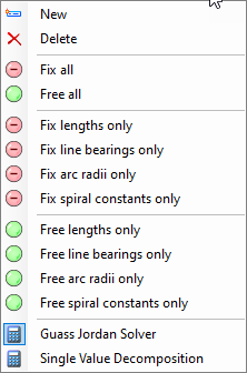
Right-Click Menu
Right-clicking in the Geometry Connector dialog will bring up the following menu:
Using the Geometry Connector tool
- Select begin element. The
begin element assumes the direction of the selected begin element. If the
direction is inappropriate return to geometry, transpose and relaunch the
Geometry Connector tool.
Selecting the begin element populates the grid in a similar manner to the Geometry Builder tool.
- Right click on the geometry type to view a menu list to specify the geometry parameters.
- Add more geometry (line, arc, spiral), if desired.
- Select end element which has the option to specify which end to connect. Use transpose to modify.
- Add to properties on
dialog. Fix or free elements.
Decorations indicate what is fixed or free.
- Fix all or free all for
large list of several elements. Fix individual parameters of all.
Same number of fix and free geometry is required to compute.
Messages of "Too many free" requires fixing more parameters or "Too many fix" requires freeing more parameters.
- When grid is ready a "Ready to compute connection" message displays and the Compute button enables.
- Apply button is enabled if successful. Apply button is grayed if a failure occurs.
- Create graphic element or
civil element. Civil elements have the option to be ruled or not.
Creating a graphic element takes elements and modified end element plus preceding element and creates new element.
Creates new geometry with no profile and simple rules.
- Report reports only green area (what is computed) not the alignment. Entire alignment can also be reported.
